Loading... Please wait...
- Call Us:317-602-1472
- My Account
-
Currency Displayed in
 Free U.S Shipping on Order over $75!
 Call Us: 317-602-1472
- Home
- Safety Standards
Categories
Popular Brands
Safety Standards
Safety Standards
Safety Standards Outline
Standards that apply to All Industrial Machines
DROP OUT & MOTOR PROTECTION
OSHA - 1910.213 (b) (3)
"On applications where injury to the operator might result if motors were to restart after a power failure, provisions shall be made to prevent machines from automatically restarting upon restoration of power."
NFPA 79 - 7.3.1 – Motor Overload Protection
“Overload devices shall be provided to protect each motor, motor controller, and branch circuit conductor against excessive heating due to motor overloads or failure to start.”
NFPA 79 - 7.5.1 – Voltage Supply Interruption
“Where a supply interruption or a voltage reduction can cause a hazardous condition or damage to the machine or to the work in progress, under voltage protection shall be provided (e.g., to switch off the machine) at a predetermined voltage level.”
NFPA 79 - 7.5.3 – Restarting & A.3.3.104 Under Voltage Protection
- ”Upon restoration of the voltage or upon switching on the incoming supply, automatic or unintentional restarting of the machine shall be prevented when such a restart can cause a hazardous condition."
- "Under voltage Protection. The principal objective of this device is to prevent automatic restarting of the equipment."
NEC 2005 – 430.43 – Automatic Restarting
A motor overload device that can restart a motor automatically after overload tripping shall not be installed if automatic restarting of the motor can result in injury to persons.
LOCK-OUT/TAG-OUT of POWER CIRCUITS
OSHA - 1910.147 (a)(1)(i) - The control of hazardousenergy
To lockout electrical energy sources:
- Unplug the machine and use an electrical plug lockout or use a disconnect switch with padlocks, lockouts, and tags.
- Disconnect and ensure that all power sources are locked and tagged out.
- Stored electrical energy must be bled to obtain zero energy state.
- Use a volt meter to make sure all circuits are dead.
NFPA 79 - 5.1.1 - Single Power Supply Circuit
“Where practicable, the electrical equipment of a machine shall be connected to a single power supply circuit.”
NFPA 79 - 5.3 – Supply Circuit Disconnecting
- “A supply circuit disconnecting means shall be provided for each incoming supply circuit to a machine.”
- “Each disconnecting means shall be legibly marked to indicate its purpose.”
- “The supply circuit disconnecting means other than attachment plugs and receptacles shall be mounted within the control enclosure or immediately adjacent thereto. Exception: Externally mounted supply circuit disconnecting means, whether interlocked or not interlocked with the control enclosure, supplying machines totaling 2 HP or less shall be permitted to be mounted up to 6 m (20 ft.) away from the enclosure providing that the disconnecting means is in sight from and readily accessible to the operator.”
- “The supply circuit disconnecting means can be an attachment plug and receptacle (plug/socket combination) for cord connection to motor loads totaling 2 HP or less.”
- “The disconnecting means shall be provided with permanent means for locking in the off position only (for other than attachment plugs).”
- “The center of the grip of the operating handle of the disconnecting means, when in its highest position, shall not be more than 2.0m (6 ft. 7 in.) above the servicing level. A permanent operating platform, readily accessible by means of a permanent stair or ladder, shall be considered as the servicing level for the purpose of this requirement.”
CONTROL CIRCUITS
NFPA 79 - 9.1 - Control Circuits
- “Control transformers shall be used for supplying the control circuits.”
- “Transformers shall not be required if the supply voltage does not exceed 120 VAC.”
- “The VAC for control circuits shall not exceed 120 VAC single phase.”
- “Control circuits shall be provided with overcurrent protection.”
NFPA 79 - 7.3.1 – Motor Overload Protection
“Overload devices shall be provided to protect each motor, motor controller, and branch circuit conductor against excessive heating due to motor overloads or failure to start.”
NFPA 79 - 9.2.2 – Stop Functions
“The three categories of stop functions shall be as follows:
- Category 0 is an uncontrolled stop by immediately removing power to the machine actuators.
- Category 1 is a controlled stop with power to the machine actuators available to achieve the stop then remove power when the stop is achieved.
- Category 2 is a controlled stop with power left available to the machine actuators.”
“Category 0, Category 1, and/or Category 2 stops shall be provided where indicated by an analysis of the risk assessment and the functional requirements of the machine.
Category 0 and Category 1 stops shall be operational regardless of operating modes, and Category 0 shall take priority. Stop function shall operate by de-energizing that relevant circuit and shall override related start functions.”
NFPA 79 - 9.2.5.4.1 – Emergency Stop Functions
Emergency stop functions shall be designed to be initiated by a single human action. In addition to the requirements for stop, 9.2.5.4.1.1 states that “the emergency stop shall have the following requirements:
1 It shall override all other functions and operations in all modes.
2 Power to the machine actuators, which causes a hazardous condition(s), shall be removed as quickly as possible without creating other hazards (e.g., by the provision of mechanical means of stopping requiring no external power, by reverse current braking for a Category 1 stop).
3 Reset of an emergency stop circuit shall not initiate a restart.
4 “Where required, provisions to connect additional emergency stop devices shall be provided.”
5 “The emergency stop shall function as either a Category 0 or a Category 1 stop. The choice of the category of the emergency stop shall be determined by the risk assessment of the machine.”
6 “Where a Category 0 stop is used for the emergency stop function, it shall have only hardwired electromechanical components.”
NFPA 79 - 9.3.6 – Protective interlocks
1 “The reclosing or resetting of an interlocking safeguard shall not initiate machine motion or operation that results in a hazardous condition.”
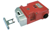
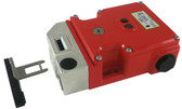
2 “Where doors or guards have interlocked switches used in circuits with Safety Related functions, the interlocking devices shall be listed safety switches, have either positive (direct) opening operation, or provide similar reliability and prevent the operation of the equipment when the doors or guards are open (difficult to defeat or bypass).”
NFPA 79 - 10.2 – Push Button Actuators
1 “Push button actuators used to initiate a stop function shall be of the extended operator or mushroom head type.”
2 “The preferred color of start or on shall be GREEN, except that BLACK, WHITE, or GRAY shall be permitted. RED shall not be used for start or on.”
3 “The preferred color for stop or off shall be RED, except that BLACK, WHITE, or GRAY shall be permitted. GREEN shall not be used for stop or off.”
4 “Push buttons that cause movement when pressed and stop movement when they are released (e.g., jogging) shall be BLACK, WHITE, GRAY, or BLUE, with a preference for BLACK.”
5 “A legend shall be provided for each operator interface device to identify its function and shall be located so that it can be easily read by the machine operator from the normal operator position. The legends shall be durable and suitable for the operating environment.”
NFPA 79 - 10.6 – Machine Start Devices
“Actuators used to initiate a start function or the movement of machine elements (e.g., slides, spindles, carriers) shall be constructed and mounted to minimize inadvertent operation.”
NFPA 79 - 10.7.1 – Emergency Stop & Stop Devices
1 “Stop and emergency stop pushbuttons shall be continuously operable and readily accessible.”
2 “Stop or emergency stop push buttons shall be located at each operator control station and at other locations where emergency stop is required.”
3 “The types of devices for emergency stop shall include, but are not limited to, the following:
(1) Push button operated switches
(2) Pull cord operated switches
(3) Foot operated switches without a mechanical guard
(4) Push bar operated switches
(5) Rod operated switches
NFPA 79 – 10.7.2 – Emergency Stop Push Buttons
1 “Pushbutton-type devices for emergency stop shall be of the self-latching type and shall have positive opening operation.”
2 “Emergency stop switches shall not be flat switches or graphic representations based on software applications.”
NFPA 79 - 10.7.3 – Emergency Stop Actuators
“Actuators of emergency stop devices shall be colored RED. The background immediately around push buttons and disconnect switch actuators used as emergency stop devices shall be colored YELLOW. The actuator of a push button operated device shall be of the palm or mushroom head type. The RED/YELLOW color combination shall be reserved exclusively for emergency stop applications.”
NFPA 79 - 10.7.5 – Supply Disconnect Emergency Stop
“The supply disconnecting means shall be permitted to be locally operated to serve the function of emergency stop where it is readily accessible to the operator, where it is a listed motor circuit switch (switch disconnect) Rated in horsepower, a listed, branch circuit rated, molded case circuit breaker, or a listed molded case switch, and where it meets the RED/YELLOW color combination.”
ANSI American National Standards Institute
IEC International Electrotechnical Commission
OSHA Occupational Safety and Health Administration
NEC National Electrical Code
NFPA National Fire Protection Association